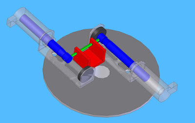
So a very smart friend of mine brought up the point of the mechanism working underwater. I didn't know. So I had to find out.
Test
Cutter Mechanism Underwater test
Objective:
To observe whether the mechanism will work in an underwater environment.
Introduction:
The cutter mechanism is going to be used in order to deflect the water from the air to the underwater piping system giving humans the illusion that the water is jumping. Each nozzle will be timed in such a way that the water will appear to be jumping or leaping from place to place.
In order to cut the water the Cutter mechanism will push and pull a plate in from of the orifice in order to deflect.
We must be certain that water will not affect the mechanism. The mechanism must be able to cutter the water in either a partially or fully submerged environment. This test is designed to find out if the water will cause any problems. We are particularly concern with the solenoids and how they will perform.
Setup
The setup for the cutter mechanism is the same as the setup in other cutter mechanism tests with the small addition on waterproofing. I applied a liberal amount of hot glue to the connections and any point that might have a leak.
I filled a 5 gallon bucket with a small amount of water just enough to cover the mechanism.
Results
The cutter mechanism was suciffiently waterproofed and I was able to contain the magic smoke. The cutter operated as designed.
The video below show the results.
Conclusion
The cutter mechanism performed well underwater. The proof of concept was succesful and the mechanism will be introduced into the design.
The mechanism was observed to be a bit slow moving from position to position, but has not be confirmed. However, the majority of the drag is probably due to the vertical plate. The Laminar Nozzle will have a significantly reduced drag since, the cutter mechanism will have a U-channel instead of an L-bracket. This should alleviate any drag induced problems.
Underwater Tests
Labels: Cutter, Electronics, Fountain, Nozzle 0 commentsJumping Laminar Jets
Labels: equations, Fountain, Nozzle 2 comments
First column
Flow Rate: This means how much water will flow through an area in a certain amount of time. This is measured in Gallons/Min. It's like how fast you would be going if you were a liquid.
Second column
Flow Rate: Same as above but just converted into different units.
Third column
Angle: This is an important one! Once we build this water fountain we will mount the nozzles at these angles
Fourth and Fifth column
Diameter and Area: The diameter is the diameter of the outlet for the water. Subsequently, the area is the calculated area for the water outlet.
Sixth column
This one is important too. This is the amount of nozzles you can have.
Seventh, Eighth, and Ninth
Velocities. The Seventh column is the total velocity, and the Eighth and Ninth are the component velocities (velocity in the horizontal and vertical directions).
Tenth, Eleventh and Twelfth
Time in the air, Height, and Distance. Pretty self explanatory.
Geekspeak:
It is all based on two principles. First, is flow in must be equal to flow out, Qin = Qout. This obviously simple equation in fact states a lot. From this equation we are able to get the exit velocity of the water because we know what the area is from whence the water is leaving. =)
Simply.
Q=v*A
solving for v
v=Q/A (Eq 1)
so Eq 1 gives us the velocity of the water leaving the nozzle. From there we can treat this like a particle motion problem. Or
h = 1/2*g*t^2 +vy*t+ho (Eq 2)
Since we are going to be putting these nozzles on an angle the velocity that we obtained from Eq 1 isn't the velocity in vo. We need to adjust the velocity for the different angles. So we need to compute the vy (velocity in the y or vertical direction).
vy = vo sin (theta)
knowing that we can calculate the total time the water is in the air. Using Eq 2 we know that the water starts from ground and ends up at the same level (ground). So h=ho = 0. Rearranging Eq 2 and solving for t you get.
t = 2*vy/g Eq 3
Using the answer from Eq 3 and subsituting it back into Eq 2 we can find the height the water will travel.
To find the distance we need one other equation. Distance = Rate * Time
or
D = vx * t
where vx = vo cos(theta) or the velocity in the horizontal direction.
Again, thanks to those who helped me with this!
Cutter Mechanism Design
Labels: Cutter, Nozzle 0 commentsDiseño e iconos por N.Design Studio | A Blogger por Blog and Web

